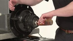
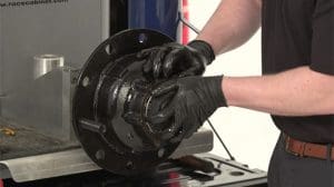
STEMCO is very conscious of the role it plays in safety. Product safety is built into the product from the initial design, considered throughout the manufacturing processes, and is accounted for in product installation. With its robust single piece design, Zip-Torq takes the guesswork out of bearing adjustment. Zip-Torq is a unitized spindle nut that uses a patented self-locking ratchet system to secure the wheel end and prevent back off.
The purpose of this tech tip is to inform customers of the proper installation methods for the Zip-Torq axle spindle nut. Zip-Torq consistently delivers accurate endplay between .001″–.005″ using the STEMCO 2-1-1 method.
We will be referencing the following STEMCO PDFs:
- Zip-Torq Installation Procedure & Bearing Adjustment
- Zip-Torq Thread Engagement Tip
- STEMCO-TQM-Catalog
Installation
*Do not use power or air tools during installation of Zip-Torq
Tools Needed for Installation
- Torque wrench
- Sockets for all applications
- Towel/and/or emery cloth to clean spindle
STEP 1: Thread the Nut Onto the Axle
Thread the nut onto the axle until hand tight.
STEP 2: Seat the Bearing
With hub or hub/drum only, use a torque wrench:
- Tighten the nut to 200 ft-lb. Spin the wheel hub assembly at least one full rotation.
- Tighten the nut to 200 ft-lb. Spin the wheel hub assembly at least one full rotation.
- Tighten the nut to 200 ft-lb. Spin the wheel hub assembly at least one full rotation.
- Back the nut off one full rotation.
With hub/drum/wheels:
- Tighten the fastener to 200 ft-lbs while the wheel is rotating.
- Back the fastener off one full turn.
STEP 3: Adjust the Bearing
With hub or hub/drum only, use a torque wrench:
- Tighten the nut to 100 ft-lb. Spin the wheel hub assembly at least one full rotation.
- Tighten the nut to 100 ft-lb. Spin the wheel hub assembly at least one full rotation.
- Tighten the nut to 100 ft-lb. Spin the wheel hub assembly at least one full rotation.
- Back the nut off one face mark (according to chart).
With hub/drum/wheels:
- Tighten the fastener to 100 ft-lbs while the wheel is rotating.
- Back the fastener off one face mark (according to chart).
STEP 4: Inspect the Installation
Failure to follow this instruction could cause the wheel to come off and cause bodily injury.
STEP 5: Inspect Keyway
Inspect keyway tang to ensure it does not contact the bottom of the keyway. If contact exists, immediately notify a STEMCO representative.
This procedure will consistently produce a bearing setting of 0.001″ to 0.003″ end play.
STEP 6: Acceptable End Play
The dial indicator should be attached to the hub or brake drum with its magnetic base.
Adjust the dial indicator so that its plunger is against the end of the spindle with its line of action approximately parallel to the axis of the spindle.
Grasp the wheel/hub assembly at the 3 o’clock and 9 o’clock positions. Pull the wheel end assembly outward while oscillating the wheel approximately 5°(between bolts holes on the hub). While continuing to pull, stop oscillating and read the indicator. (Note position of dial indicator)
Push the wheel assembly inward while oscillating. While continuing to push, stop oscillating at same position as it was before in the pull direction and read the indicator. Read bearing end play as total indicator movement.
*Acceptable end-play is .001″ – .005″
| Final Backoff | |
|---|---|
| ZIP-TORQ® | Backoff |
| Trailer Axle Fastener® | |
| 400-4723 | 1/8 turn |
| 400-4743 | 1/4 turn |
| Steering Axle Fastener | |
| 400-4836 | 1/8 turn |
| 400-4837 | 1/3 turn |
| 400-4864 | 1/4 turn |
| 400-4865 | 1/8 turn |
| Drive Axle Fastener | |
| 400-4904 | 1/8 turn |
| 400-4973 | 1/8 turn |
If you would like more information on our STEMCO Zip-Torq unitized spindle nut, visit our product page.
To access our full library of Tech Tips, click here.
For in-depth articles covering industry news and trends, product spotlights, case studies, customer insights, and “thought leadership” topics from STEMCO professionals, visit The Wheelhouse Blog.


