Staying up to date on your equipment maintenance in the trucking industry requires accurate, reliable information, and nothing delivers it like our digital and mechanical Hubodometers
The purpose of this tech tip is to inform customers of the proper installation method for STEMCO Hubodometers. We will be referencing the following STEMCO PDFs:
- Hubodometer and Bracket Installation Instructions
- Installation Instructions for STEMCO Hubodometer Mount
- Installation Instructions for STEMCO Hubodometer
Bracket Installation
NOTE: LUBRICANT MAY NEED TO BE ADDED PRIOR TO BRACKET INSTALLATION.
STEP 1
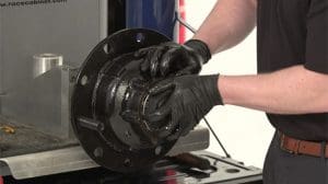
Install hub cap with proper gaskets and installation methods provided by hub cap manufacturer.
STEP 2
Split lock washers are recommended to secure the hub cap bolts in place.
STEP 3
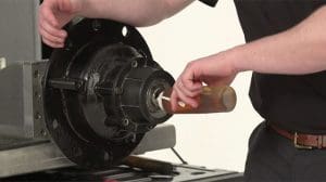
Fill to proper lubricant level.
STEP 4
Mount Hubodometer to face of bracket using the supplied flat washer and lock nut.
STEP 5
Use 15-ft lbs. of torque to tighten locknut.
- Do not use an air impact wrench.
- Do not exceed 15-ft. lbs. of torque.
STEP 6
If necessary, use strap wrench to hold Hubodometer while tightening.
STEP 7
Do not use paints, solvents or thinners on the Hubodometer face, grilamid hub cap or hubodometer hub cap window.
STEP 8
Remove necessary bolts for bracket installation. Some lubricant may drain. refill as necessary.
STEP 9
Mount bracket and Hubodometer assembly.
STEP 10
Split lock washers are recommended to secure the bolts in place.
STEP 11
Proper length grade 5 or higher bolts are recommended to secure Hubodometer bracket.
STEP 12
Torque bolts to the recommended hub cap torque specifications. The recommended torque for the 3/8″ pipe plug for aluminum hub caps is 9 ft.-lbs. A suitable sealant may be used on the pipe plug threads if desired.
On Grilamid hub caps with plastic fill plug and o-ring, tighten to torque not to exceed 10 ft. lbs.
Hubodometer Installation
STEP 1
Mount Hubodometer to face of hub cap or bracket.
STEP 2
Use washer under locknut.
STEP 3
Set 15 ft-lbs. of torque to tighten locknut. Do not exceed 15 ft-lbs. of torque.
STEP 4
If necessary, use strap wrench to hold Hubodometer while tightening.
STEP 5
Do not use paints, solvents or thinner on the Hubodometer face or on the plastic hub caps. Do not weld on the Hubodometer.
Installation Instructions for STEMCO Hubodometer – Rear Wheel Truck or Bus Mount
(Part Numbers 610-0011 and 610-0025)
STEP 1
Drill two 3/16″ holes on each end of mounting strap at marks corresponding to bolt circle diameter of rear wheel axle
STEP 2
Open single hole in support angles if necessary to fit axle studs or bolts.
STEP 3
Cut and trim strap 3/8″ beyond rivet holes on both ends.
STEP 4
Assemble angles to mounting strap using 4 rivets supplied. Trim angles to conform to contour of axle if necessary.
STEP 5
Place washer on Hubodometer stud.
STEP 6
Mount Hubodometer on strap using 1/2″ locknut supplied. It is recommended that a strap wrench be used to hold Hubodometer while tightening. Do not clamp Hubodometer flange in a vise. Do not exceed 15 ft/lbs torque.
STEP 7
Mount strap assembly to axle.
STEP 8
To clean Hubodometer face, use a damp cloth to prevent scratches. Do not use solvents, paints or thinners.
If you would like more information on STEMCO hubodometers, visit our product page.
To access our full library of Tech Tips, click here.”>click here.
For in-depth articles covering industry news and trends, product spotlights, case studies, customer insights, and “thought leadership” topics from STEMCO professionals, visit The Wheelhouse Blog.


